
This timeline of lighting control systems can be viewed at White Light in Wimbledon, London.
It’s curated by Jim Laws, who donated most of the equipment for the displays. Many thanks go out to Chris Nicholls at White Light for being so enthusiastic about preserving this equipment, and rearranging their storage areas to accommodate it.
Click on the exhibits below to view the entry on the Backstage Heritage Collection database.
See also History of Lighting Control
THIS PAGE IS UNDER CONSTRUCTION
Control Desks
Direct Control
- Grand Master (1930s – 1950s)
Huge manually-operated control, where levers directly controlled resistance dimmers mounted just behind them. Grouping was done by screwing controls onto a ‘master’ control shaft, which was then turned to control all of the dimmers that were ‘grouped’ onto it.
More about Grand Master - Bracket Handle ()
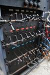
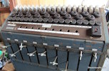
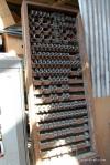
- Versa Dim Master Switchboard 9 way dimmer rack (1940s – 1960s)
Gaumont British 9 way dimmer rack (supplied with 30 Amps of electricity) with 18 channels. This is badged Rank Audio Visual, as the Rank organisation bought a controlling share in the Gaumont British company in 1941.
Each channel can be either controlled by one of 9 dimmers, or can be full on, or off.
Dimmers are controlled by the silver levers at the front of the rack, either individually, or can be locked on to the master control, which allows multiple dimmers to be faded simultaneously by turning the wheel at the side.

 Versa Dim Master Stage Switchboard (9 way) (1942)
18 channels into 9 dimmers.
From Jim Laws Collection
- Siemens Bordoni
A more sophisticated, and energy-efficient system was made by Siemens / AEG in Germany, based on a system devised by Bordoni. These were the standard way of dimming in central Europe, and used an autotransformer instead of a resistance (the preferred British method), and allowed the operator to preset levels more accurately, and also to drive some dimmers up, and others down, as part of the same cue.
As Francis Reid says in Cue issue 45 (page 18):
“Each circuit had its own secondary winding which slid in and out of the transformer, moved by a tracker wire from a central control frame with banks of levers. Circuits could accept any load from about 40 watts to 6 kilowatt. Such autotransformers never caught on in Britain except at Glyndebourne where a Bordoni ruled from 1934 to 1963.”
More about the Bordoni system
Remote Control
As the desire developed for more elaborate control of large quantities of dimmers, it became necessary to find a way to remotely control the dimmers, instead of the direct control methods above.
Strand Electric’s Fred Bentham came up with the idea of using the same technology that Compton used to make a keyboard remotely control valves feeding massive organ pipes. He developed the Light Console in 1935, enabling the lighting operator to be in a position where he/she could see the stage.
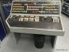
- Light Console
In 1950, the largest Light Console was built for Theatre Royal, Drury Lane, with 216 ways, and effectively automated the functions of the Grand Master.
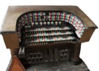 Light Console, Theatre Royal Drury Lane (1950)
3 manuals, 216 ways, 6 speeds. The largest of the Light Consoles, and one of only 14 made.
From Jim Laws Collection
Operationally unlike anything before or since, the Light Console used organ ‘stops’ to enable the presetting or grouping of dimmers, and the command keys on the three keyboards to move dimmers up or down. Foot pedals controlled the speed of fades, and enabled blackouts to take place. The coloured command keys related to colour-coded groups of dimmers, geographically in the same place on the console. The console controlled
For more information, see the documents on the link above.
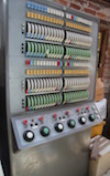
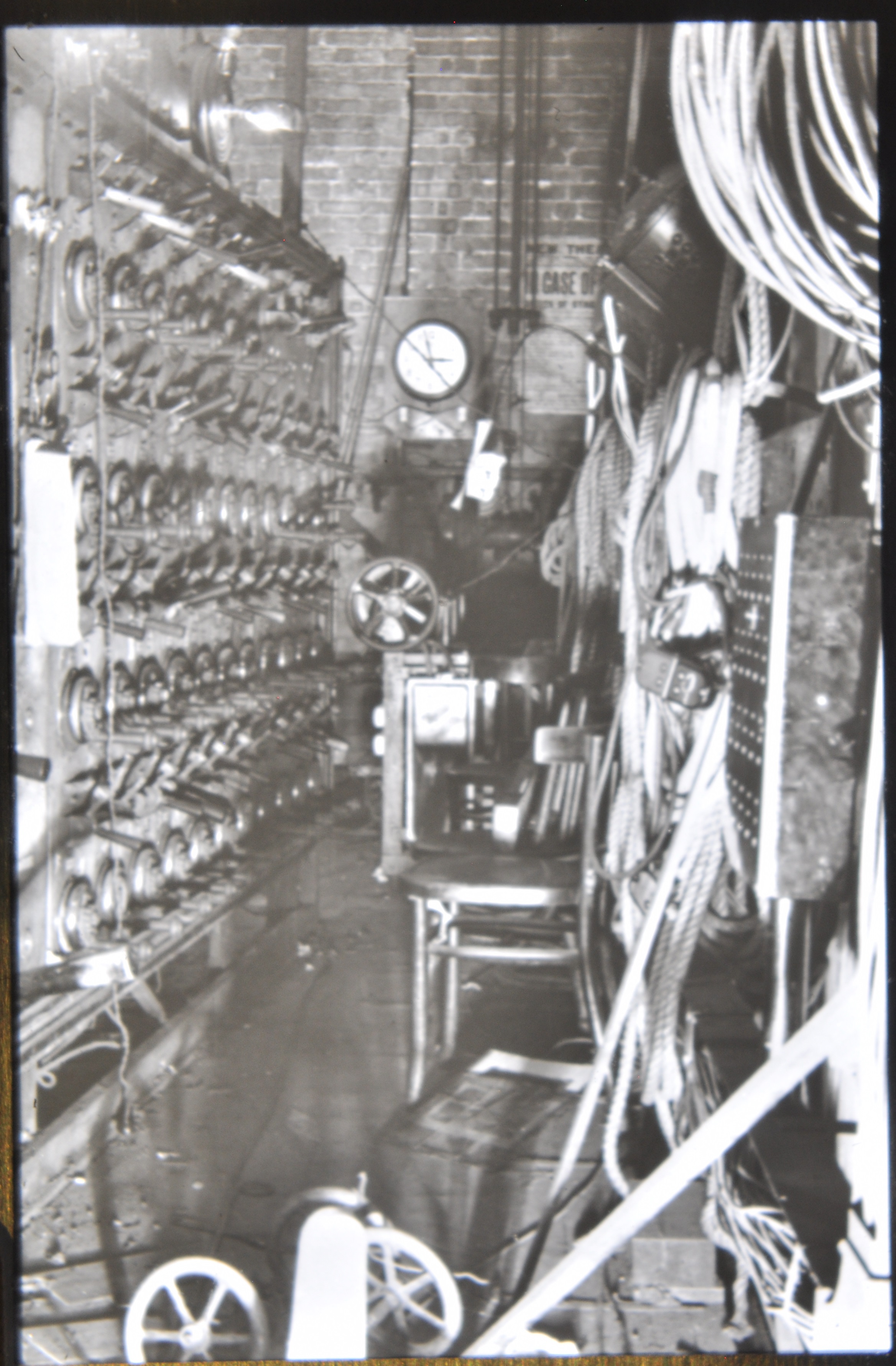
The relay bank below shows some of the complexity of the system – the bank of relays stored and passed on commands from the Light Console for the Theatre Royal, Bristol (60 dimmer channels). The console was built in 1946 and represented the state of the art at that time.
At the bottom of the relay bank there’s a panel where voltages can be read and checked to assist with fault-finding etc. along with a transformer and a large fuse to deal with the current needed to power the relays (with electromagnets).
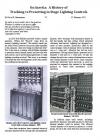
On Inertia - A History of Tracking vs Presetting in Lighting Controls (February 2021)
[1.17Mb PDF]
From David Bertenshaw Collection
Memory Consoles
Punched Cards
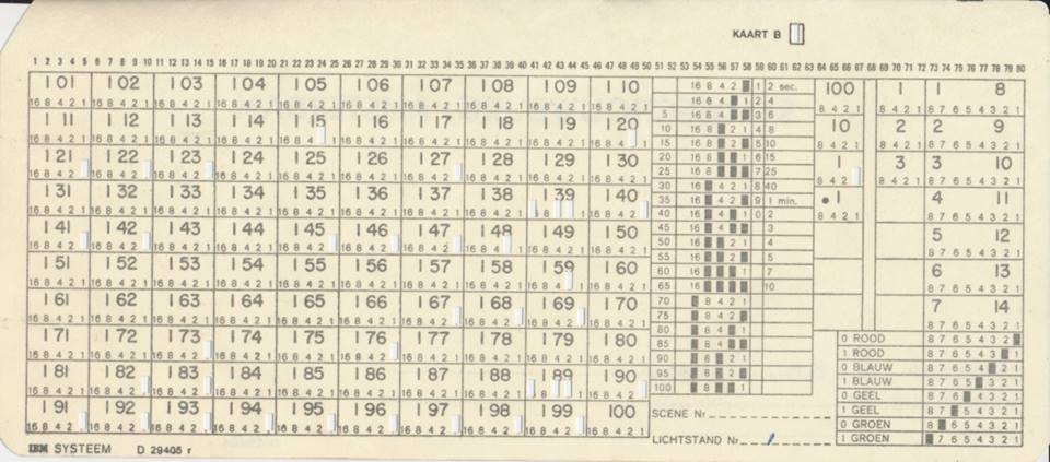
In the early days of computing, the technology of hard disks and re-writable memory cards did not exist, so in order to ‘memorise’ lighting states, punched cards were used, which were then fed into the lighting computer in order, to recall the cue. Mechanical pins ‘read’ the information from the card on insertion, which was then made into the current lighting state on command. The cards for the next state were then inserted.
The card shown below is from a lighting control desk in the Amsterdam Municipal Theatre (Stadsschouwburg) and was in use in the 1970s and 1980s.
Each lighting state (cue) used two cards, one for channels 1-100, the second for 101-200. The levels for each channel were encoded in 5% increments (so only 25% or 30% were possible, not 28%).
Columns 64-67 were used to encode the cue number. Columns 69-72 encoded the crossfade time, and columns 73-80 were used to control the mechanical colour changers (most likely semaphore type) in some FOH positions.
Many thanks to Roderick Van Gelder for posting this information.
Software-configurable lighting control desk
The industry-standard theatre desk in the UK for many years was the 500 series by Strand Lighting. Used on shows large and small, it was based around a low-specification PC running a modified version of Microsoft’s DOS language. Almost every function on the desk can be configured, and by updating the operating system, a completely new set of functions can be added.
Historical Overview
Dimming
- Liquid Dimmers
Also known as Salt Water Dimmers (and colloquially known as ‘pisspot dimmers’.)
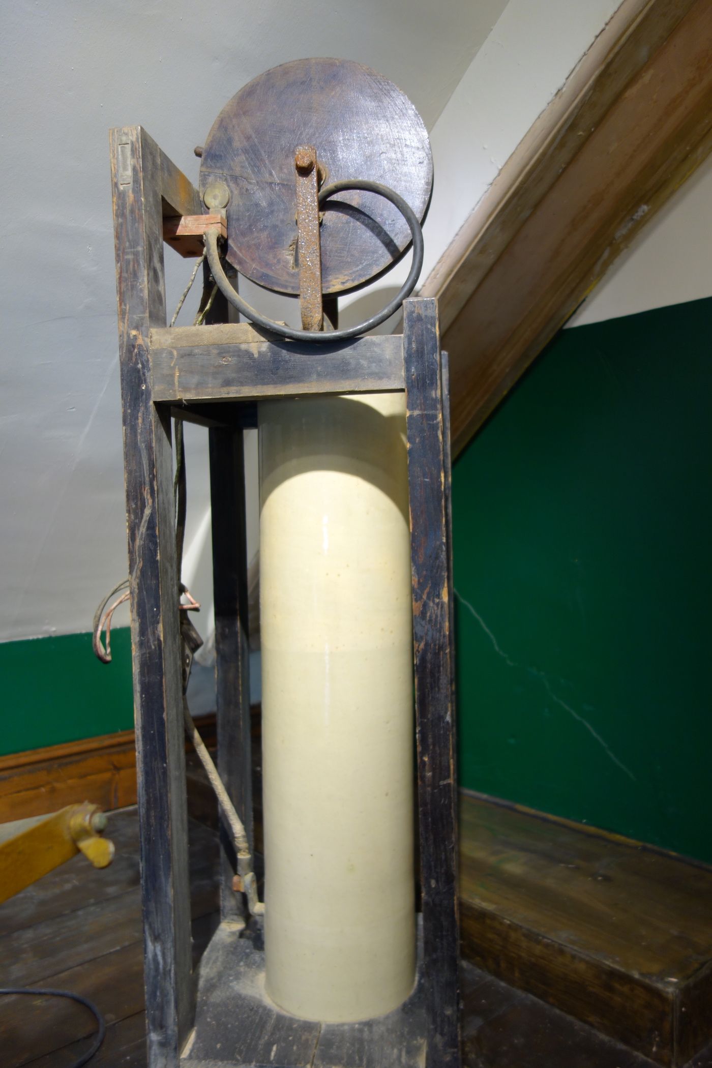
Liquid Dimmer at the Gaiety Theatre
Click on thumbnail to enlarge
[721kb JPEG]
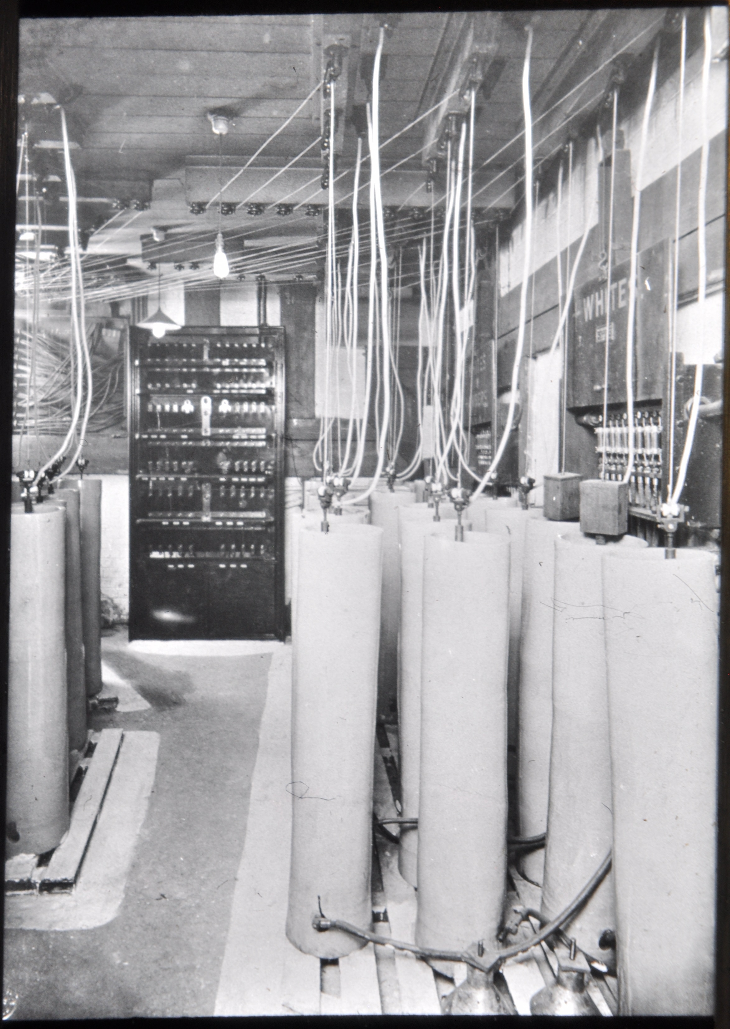
M194 London Coliseum Liquid Dimmers
Click on thumbnail to enlarge
[1.59Mb JPEG]
From Strand Slide Archive
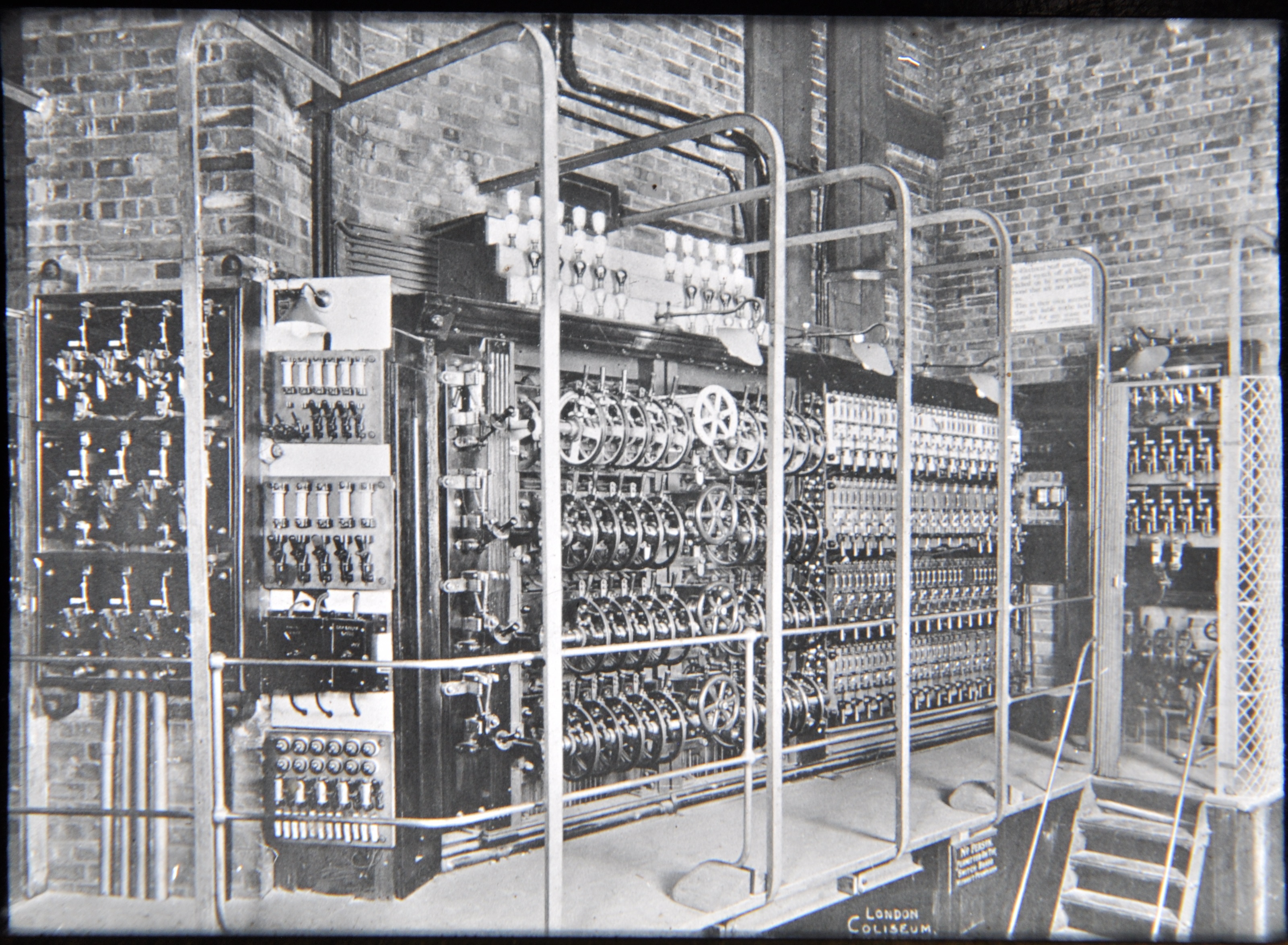
M193 London Coliseum Liquid Dimmer Control
Click on thumbnail to enlarge
[2.2Mb JPEG]
From Strand Slide Archive
M294 New now Albery Theatre liquid dimmers c.1950 (1950)
Click on thumbnail to enlarge
[1.66Mb JPEG]
From Strand Slide Archive
Thyristor Dimmer Control
Communication between Control Desk and Dimmers
Multiplexed Signal – Analogue
This was the first step towards the lighting control protocol we use today. Rather than wire-per-dimmer systems, which rely on a huge amount of expensive copper wiring from the control desk to the dimmers, making it difficult and time-consuming to move the desk for a complex system, a multiplex system is a serial system of communication – control levels are sent down a single cable, in a repeating sequence of channel numbers.
A serial stream of (originally) analogue voltages with strict timing separations which enabled a de-multiplexing (‘demux’) microprocessor interface to ‘decode’ the signal and allocate the different voltages to a specific lighting channel.
In the USA, Strand Lighting developed AMX192 (US Standard, introduced around 1975, known as AMX) could control up to 192 channels and used a 4-pin XLR connector. (AMX stands for Analogue Multiplex). Later desks were able to support multiple streams of AMX to increase the number of channels supported. The protocol used a separate clock pulse generator which ran in each device that used AMX.
Around the same time in the UK, Strand developed D54 protocol which was similar to AMX192, but was able to carry up to 384 voltage values for that many channels, along with a more strict clock pulse, embedded within the control signal, to keep the desk and dimmers synchronised properly. D54 used a 3-pin XLR connector.
Both AMX192 and D54 have now largely been replaced by the universally used digital protocol USITT DMX512 (see below).
Digital Control (DMX512)
Officially known as USITT DMX512 but often shortened to DMX, this protocol was introduced in 1986, and is based on the RS485 data standard. Most professional lighting desks use 5-pin XLR connectors, but cheaper equipment and many moving lights or LED fittings use the cheaper 3-pin XLR connector, although this is not supported in the USITT standard.
Wiring for DMX512
| Pin number | 1 | 2 | 3 | 4 | 5 |
| 3 pin XLR | Shield | negative | positive | ||
| 5 pin XLR | Shield | negative | positive | NC | NC |
(NB: The shield should not be connected to the body of the connector. NC = Not Connected)
Evolution
As technologies change, new protocols (or new versions of existing protocols) are introduced:
SMX is a communications protocol which enables digital dimmers to “report back” to the desk on any faults (eg blown lamps).
DMX512-A (officially ANSI E1.11) is a new standard under development at ESTA which is backwards compatible with DMX512 but has stricter safety parameters and offers some upgrades of functionality.
RDM (Remote Device Management)
RDM is an emerging upgrade to DMX512 which will include bi-directional communication between controller and device. It’s officially known as ANSI E1.20, Remote Device Management.
As well as controlling devices, it also allows remote configuration of instruments. This could include basic setup such as setting start addresses (which could be done automatically by a computerised system; this alone could save hours).
Although manufacturer uptake is limited so far, it’s hoped this situation will change soon.
Keywords: Lighting Control History, History of Lighting Control, On Inertia – A History of Tracking vs Presetting in Lighting, on inertia a history of tracking vs presetting in stage lighting controls