
The Lighting System
At its simplest, a lighting system consists of electricity, dimmers, cables, lanterns and a control desk with a connection to the dimmers.
In the past, the control desk was manual and had a single cable from each fader / channel to the control desk. Larger systems used more cables, and became harder to navigate.
The only options you had were deciding which lanterns plugged into which sockets on the rig, and (sometimes) which dimmers they were connected to.
Basic Lighting System (UK)
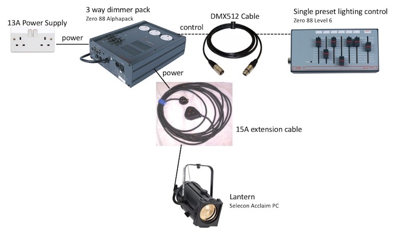
Basic lighting system connections (c) Theatrecrafts.com 2018
Small Theatre Lighting System (UK)
3 x 12 way dimmer racks give you 36 dimmer channels.
One rack (12 dimmers) shown below. The dimmer racks connect to the lighting bars via multicore ‘Socapex’ cables. Using a single multicore cable is far easier than running 6 separate 15A cables all the way from the dimmer racks to the lanterns.
(See Flexible Lighting Installation below for more)
13A or 15A
In the UK, 13A sockets and plugs are used for most purposes around the home / office environment. The 3-pin plugs have a built-in fuse, which protects the appliance and cable in the event of a fault.
Many theatres still use the older-type 15A plugs and sockets. These use round pins, and are more suited to heavy duty use, and do not have a fuse in the plugtop. Every dimmer circuit that feeds a stage lantern is protected by a fuse (usually 10 Amps) which means that in the event of a fault or if a lamp blows, only one fuse will need to be replaced. When a lamp fails, often accompanied by a bright white flash, a large current can flow, which usually causes the fuse to blow – if there were multiple fuses in plugs between the dimmer and the lighting bar, it would be very time-consuming each time this regular event occurs.
If 15A plugs / sockets are used as part of a hot power / constant power system, to provide power to LEDs, moving lights etc, then there should be a fuse easily accessible at the source of the power before the first 15A connection.
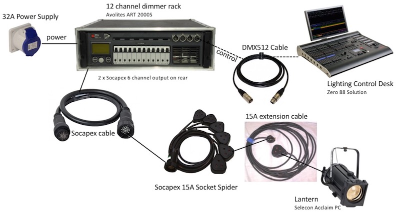
Lighting system using Socapex cable to connect dimmers to lanterns (c) Theatrecrafts.com 2018
Touring Lighting System
Electrical generator supplies 3 phase power over CamLok cables to a distribution board, which provides a separate power supply (with circuit breaker) to each of the dimmer racks, each of which feeds a different physical part of the rig.
ILLUSTRATION COMING SOON
System Overview
- Electrical Supply & Distribution board
Supplies sufficient power to the different elements of the stage lighting system, and provides protection to ensure the system is not overloaded.
- Dimmer packs
Vary the amount of electrical power fed to the lighting rig under the control of the lighting desk. - Electrical Cabling & patching
Connects the dimmer packs to the lanterns - Grid / bars / rigging positions
Variety of possible places you can rig a lantern and connect to electrical cabling - Lanterns
Different types of lantern produce different qualities / intensity of light. - Colour gel
Different gels can be placed in front of each lantern to vary the effect of the light - Control cabling
Connects the dimmer packs to the control desk - Control desk
Enables the lighting operator to remotely control the dimmer levels.
Evolution
The two parts of the lighting system, power and control, were separate. A large electrical supply went to the dimmers, which fed power to the lanterns. The control side of things only went between the control desk and the dimmers.
This started to shift when electrically powered semaphore colour changers appeared. Initially, these mechanical devices had their own control box, which wasn’t part of the lighting desk. In the National Theatre’s Lightboard, introduced in 1975, the controls for colour change were brought into the control desk for the first time. There was a separate set of wiring to the colour changers, so it wasn’t a fully integrated system.
Multiplexed control systems, introduced in the 1980s, first enabled a single cable to link from the control desk to dimmers, and once DMX512 was introduced in 1986, it was a short step to controlling other devices. Colour scrollers, which evolved from the semaphore colour changers, tended to use their own cable, consisting of a 24 volt power feed as well as a data feed. A DMX512 signal would go to a scroller control box, which converted DMX into a proprietary protocol for each scroller manufacturer. The early moving lights (such as those from Vari*Lite) used their own protocol, and it was only in the early 1990s that DMX512 started to be used to control them. Lighting rigs then started to need non-dimmed (constant) power feeds to moving lights, as well as DMX512 networks to control them.
What is patching?
Patching describes the act of connecting different parts of the lighting or sound system together.
For example, some stage lighting installations have dimmers which are wall-mounted above a row of plugs, which can be used to connect any plug into any dimmer.
A lighting system can generate a lot of data, so it’s important to be aware of the following, and to make notes of the numbers where relevant.
Socket Number on the Bar
Each socket in the lighting rig should be separately identified. The numbers are only relevant when you’re working out the dimmer numbers and physical location of the lanterns. Once the lantern has a dimmer number, the socket number is no longer relevant, unless the lantern needs specific attention.
Multicore Number (if exists)
Some systems have multicore power cables connecting between lighting bars and dimmers. These multicores may be lettered and numbered (e.g. A1, A2 through to A6, then B1 etc.). Other systems have direct connections from the sockets on the rig to a hard patch next to the dimmers (see below)
Dimmer Number
The dimmer number is often the same as the channel number on the control desk (but not always). It’s needed if the dimmer fuse / circuit breaker trips out.
Channel Number
The control channel on the lighting desk (which is often the dimmer number, but not always if a soft patch has changed the default settings).
DMX Address
An address must be set on each piece of equipment that is connected to the DMX network, so that it knows what DMX level from the lighting desk it should respond to.
Fixed Rigs – Drama Studio
Hard Patch: Dimmers to lanterns
A system using physical cables to connect into equipment uses a hard patch (i.e. a hardware patch).
Most commonly, you can connect circuits on the rig (sockets on the lighting bars) to dimmers.
15A Patch (UK)


The studio shown below (studio TS3 at the University of Exeter Drama Department) had 36 outlets around the room, and a total of 18 dimmers.
The hard patch above allowed any of the 36 circuits to be connected to any of the dimmers.
As each dimmer channel on the Zero 88 Betapack had two sockets, it was possible to connect two circuits into each dimmer, but then they would both be ‘on’ at the same time, which may not work for all productions.
The patching system was replaced in 2019 with a new set of dimmers which are switchable (using a bypass switch) between dimmable power and ‘hot’ power, which enables LED wash lights, moving lights etc to be connected into the rig more easily. There are also now 36 dimmers, so that each socket on the rig is permanently connected to the system, and only needs to be turned on, either by dimmer, or by pressing the bypass switch to send constant power to it.


PowerCon Patch
This installation, Roborough Studios at the University of Exeter Drama Department, uses PowerCon patch cables to connect dimmer outlets to rig circuits. The panel directly above the dimmer racks contains feeds from the dimmers (two dimmer outlets per dimmer channel). The panel adjacent to it feeds the sockets on the lighting rigs in the studios.
> Link to powerCon page on the Neutrik website


Flexible Lighting Installation
A large theatre requires much more control over where dimmer circuits appear, and the ability to redistribute them easily.
A system of multicore cables is used to connect the dimmers to the lighting bars, which are often internally-wired, and moveable.
Socapex
Each Socapex connector consists of either 19 pins (6 dimmer channels = 6 lives, 6 neutrals, 6 earths, plus an alignment pin) or 37 pins (12 dimmer channels = 12 lives, 12 neutrals, 12 earths plus alignment). Socapex is often abbreviated to Soca.
Lectriflex
Each Lectriflex connector (for stage lighting use) consists of 16 pins (6 dimmer channels = 6 lives, 6 neutrals, 4 earths shared).
DMX Connections
DMX512 (shortened to DMX) is a Digital Multiplexed control protocol used to link control desks to dimmers and other devices that can be controlled by DMX.
The system shown at the top of this page uses analogue control – each control channel on the desk has a separate connection to each dimmer. These are usually grouped in 6s. So a 12 channel control desk would have 2 x 6 way control cables, one going to each 6 way dimmer. As systems scale up, with some venues having many hundreds of dimmers, this becomes very cumbersome.
DMX512 is a digital signal which runs down a single data cable from the control desk and carries level information for 512 channels at a time.
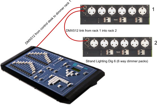
DMX512 connections from lighting control desk (Strand 200 Series) to dimmer racks (Strand DIG6)
A simple system has only dimmers, where the number of DMX channels required is equal to the number of dimmers.
As well as a DMX feed from the control desks, the dimmer packs require a constant power supply (usually from the building’s main power intake room, rather than being plugged into a general use socket, so that a large amount of power is available). See Dimmers Watts and Fuses for more information.
A generic lantern (non-LED and non-moving) such as a fresnel or a parcan is fed with dimmed power from the dimmer rack.
However, modern lighting systems consist of more than just dimmers. Any LED instrument or moving light requires a constant (non-dimmed) power supply, along with a DMX control signal to tell it what to do. As the lighting instrument gets more complex, it requires more DMX channels.
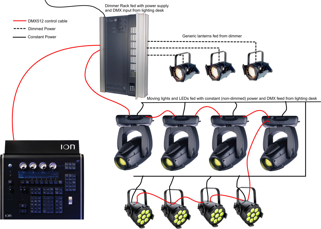
ETC Ion control desk connected to a Zero 88 Chilli dimmer rack, 4 x Vari*Lite 3000 and 4 x ETC Color Source Par, all on a single run of DMX512. Dimmed and constant power feeds are also shown for clarity.
In the diagram above, the fused rating of the power supply must not be exceeded, so more than one power circuit should be used for the moving lights and LED Pars. Some low-wattage fixtures have the ability to connect a power output to an adjacent fixture, so that the need for additional cabling is reduced. Check the manufacturers instructions for the maximum number of fixtures that can be daisy-chained together in this way.
A colour-changing LED instrument needs (at least) 3 channels – one for each of the colours (Red, Green, Blue). Some LEDs use even more channels (adding Amber and/or White, and even more for high-end instruments from companies such as ETC, along with controls for strobe functions & resetting).
‘Intelligent’ moving lights need even more DMX channels.
DMX Address
Each device on the DMX network must be given a specific ‘address’, which sets the first DMX channel it should respond to. In the diagram above, for example, the first dimmer rack could be set to ‘1’. This rack would then be controlled by channels 1-24. The second rack could be set to start at ’25’, so that it’s controlled by channels 25-48. (If you set both racks to DMX 1, they would both respond to the same channels).
The Vari*LIte 3000 spot actually uses 28 channels per instrument, so the first one would be addressed to ’49’, then ’77’, then ‘105’ and so on.
The Color Source LED uses 6 channels per instrument.
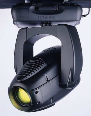
Vari*Lite 3000 Spot (c) Vari*Lite
For interest, the Vari*Lite 3000 Spot uses the following control channels:
01: Intensity
02: Pan (Coarse)
03: Pan (Fine)
04: Tilt (Coarse)
05: Tilt (Fine)
06: Edge (Focus)
07: Zoom (Size)
08: Color Temperature mixer (CTO Mixer)
09: Blue Mixer
10: Amber Mixer
11: Magenta Mixer
12: Color Wheel
13: Gobo Wheel 1
14: Gobo 1 Index (Coarse)
15: Gobo 1 Index (Fine)
16: Gobo Wheel 2
17: Gobo 2 Index (Coarse)
18: Gobo 2 Index (Fine)
19: Gobo Wheel 3
20 Gobo 3 Index (Coarse)
21: Gobo 3 Index (Fine)
22: Beam Iris
23: Strobe
24: Focus Time
25: Color Time
26: Beam Time
27: Gobo Time
28: Control
DMX Universe
Each DMX output from a lighting desk can handle 512 channels of information. Each group of 512 channels is known as a DMX Universe. A large or complex venue or system might need more than 512 channels. Any system with more than one DMX universe must refer to the universe number when describing DMX addresses. DMX channel 49 on the second universe will be 2/49 (on ETC systems) or 2.49 (on Avolites systems).
Large computerised desks can support multiple universes, and massive systems.
DMX Terminator
At the end of a ‘run’ of DMX512, you should use a DMX Terminator. This consists of an electronic component called a resistor inside a DMX connector, which acts to absorb the signal to stop it reflecting back along the cable and corrupting the signal.
DIAGRAM – DMX TERMINATOR.
Soft Patch: Control channels to DMX outputs
Most computerised lighting desks (and many manual ones) enable you to patch channels (i.e. faders on the desk) to dimmers (i.e. DMX outputs).
This means that the lighting technician can set channel 1 on the desk to control (for example) either just channel 1 (which would be the default / standard patch) or channels 4 and 12, or any other combination. This is useful because dimmers doing the same sort of job (e.g. general wash) can be arranged next to each other on the control desk.
Sensible Numbering, Not Geography
Some venue systems do not allow you to hard patch dimmer outputs, so you’re stuck with a set of dimmer numbers which relate only to the geography of the venue. (e.g. Dimmers 1-40 are front of house, dimmers 41 – 65 are on the first LX bar, and so on). This makes it almost impossible to recall groups of numbers.
If the downstage right general wash is numbers 4, 16 and 43 (for example), that’s more tricky to remember than it being repatched to be 1,2,3 on the control desk. Channel 1 would be soft-patched to dimmer 4. Channel 2 would be soft-patched to dimmer 16, and so on.
Touring
The most common use for soft-patching is to ensure that the channel numbers on the control desk always relate to the same lanterns in the rig, regardless of which venue the show is touring into. This means a toured lighting desk has the show saved onto it, and it will work the same in every venue as long as the control channels are soft-patched to the correct dimmer numbers that apply to that venue.
Three Phase Systems (UK)
Buildings / companies with large electrical requirements (such as theatres) usually have a Three Phase electrical supply. This is the most efficient way to get a large amount of electrical power from the generator to the end user.
MORE COMING SOON
DMX512 Cable
DMX systems require 3 connections – a twisted pair of cables wrapped with a foil shield (to reduce interference from other electrical equipment).
The standard connector for DMX is a 5 pin XLR. However, many cheap DMX devices use 3 pin XLR connectors which enable you to use standard 3 pin audio/microphone cables. However, although this will often work, it’s far more susceptible to interference from other systems, and is not the professional way of connecting DMX devices together. The impedance (electrical resistance) of audio cable is different from that of DMX cable, and will result in a degraded signal on large systems. You may find that this is not a problem on your system, and that you can get away with using microphone cable, but please remember that if the system stops responding correctly to DMX signals during the show, finding the cable causing the problem is not a quick job, and the resulting effect on your show (and your reputation) will be negative.
The correct solution is to use DMX512 cables to carry DMX512 signals, and to use audio cable for microphones etc. Any other solution puts your show at risk of failure.
Towards the Future
DMX512 is inherently limited (to 512 channels) and is relatively slow by modern computing standards (it was first created in 1986). While that’s not a problem for most small to medium-scale theatres, it becomes an issue when lots of moving lights are used, or, increasingly LED fixtures used as pixels.
There are a number of protocols battling to replace (or at least enhance) DMX512.
The Use of Networking in Theatrical Lighting Applications (1998)
[2Mb PDF]
From Richard Bunting Collection
Existing cabling
RDM: Remote Device Management – enables bi-directional communication between the control desk and the dimmer (or fixture) using standard DMX512 cables.
Ethernet cabling
In the late 1990s standards began to be developed to make use of computer network cabling to carry control signals for entertainment lighting. The cable is cheaper than DMX512 and allows a greater amount of data to be carried with accuracy over long distances.
Art-Net: A data distribution protocol developed and owned by Artistic Licence, which allows DMX512 and RDM signals to be transmitted on a single Ethernet cable. The protocol allows multiple universes of DMX512 (up to 32768 universes!) to be carried on a single cable, overcoming the main limited factor using DMX512 on large systems. The protocol is regularly updated to make use of advances in technology, and to cope with the demands of expanding systems.
More about Art-Net.
Streaming RDM / RDMnet: The colloquial name for ANSI BSR E1.33 – a developing standard that allows RDM data (see above) to be streamed over a network.
s-ACN / Streaming ACN: When combined with RDMnet, s-ACN is similar in many ways to Art-Net. This standard has been developed by ESTA, and is officially known as ANSI E1.31-2009.
More Information?
If you’d like more detail on any of the above, or if the information you need is not here, please Contact Us and we’ll happily add more detail!
Last updated: May 2019
Lighting Patching, Patching Lights, Light Patching, Patching Lighting, LX Patching, What is Patching, Soft Patch, Hard Patch vs Soft Patch, Patch vs Address, Patching Schedule, Patch Schedule, lighting signal flow, use 13 amp or 15 amp, using 13 amp of 15 amp, use 13A or 15A, use 13amp or 15amp, difference between 13A and 15A