1.1 Mini-2+ Portable Dimmer Packs (Drawing No. 7B15387)
Mini-2+ Dimmer Packs are not identical with previous Mini-2
packs. The VISUAL difference is that Mini-2+ packs have the
fuses together in one block on the right hand side and the dimmer
modules (which are not interchangable with previous Mini-2)
have the fixing screws off-centre from the vertical.
Each Mini-2+ dimmer pack contains six self-contained 2kW Thyristor dimmer modules with twin, paralleled socket outlets. There are three variants of the dimmer pack as follows :-
Reyrolle Pullcap fused, with 15 amp 3-pin socket outlets, single phase input.
Pack code 04 784 08
Spare HRC fuse-links are 10 amp LC.10A (code 08 562 09 for a packet of 10) which fit the BLUE pullcap carriers (spares code 08 095 04 for a packet of 10).
Reyrolle Pullcap fused, with 5 amp 3-pin socket outlets, single phase input.
Pack code 04 757 02
Spare fuse-links are 10 amp LC.10A fitting BLUE pullcap carriers. Each 5 amp socket also has a 5 amp 20 x 5mm CERAMIC fuse-link (code 08 005 17 for a packet of 10).
Neozed fused, with 16 amp 2 pole + E Schuko socket outlets, three phase input (not suitable for U.K. use).
Pack code 04 785 03
Spare HRC fuse-links are 10 amp Neozed FLINKE (code 08 001 31 for packet of 10). Spare Neozed fuse caps are also available (code 08 002 37 for a packet of 10).
Each dimmer module is secured at the front by two screws, offset from the vertical, and connected electrically via a 6 way terminal block mounted on the rear of the module. The rear cover of each pack provides the easiest access to the terminal block and the trigger card.
A cable gland is provided in the right hand end of each pack for the incoming mains supply, which must contain an earth/ground connector. Input terminals are rail-mounted pressure-pad terminals for phase, neutral and earth mounted behind the blank panel on the right hand side. The solid busbar behind the fuses is fed by a full cross-section conductor direct from the phase input terminal(s). From the other side of the fuse-link the six dimmer modules are fed individually via the cable harness. The individual neutral return conductors are commoned at the mains input terminal, and the earth/ground conductors are commoned at the rack earth stud.
The serial number of each dimmer pack is stamped on a small plate immediately above the mains input terminals.
An extra-low voltage (-15v DC) power supply (described later) for the desk is built into a separate compartment behind the main input terminals.
The -15v DC feed for the desk and the dimmer control connections are via an 8-pin International octal socket mounted in the right hand end of each pack.
The sequence, and insulation colours, are as follows:-
Channel 1       Pin 1       Slate

        2           2       Brown

        3           3       Pink

        4           4       Orange

        5           5       Yellow

        6           6       Violet

-15v DC to desk     7       Blue

Common (earth/gnd)  8       Green/Yellow
1.2 Perma 12 Racks (Drawing no. 7A17537)
Each Perma 12 Rack contains twelve self-contained 2kW Thyristor dimmer modules, identical to Mini-2+ modules except that no socket outlets are fitted, and the modules are reverse-mounted. Output connections are wired to terminals in the connection area, at the bottom right hand side, for 'hard' external wiring.
There are two variants as follows :-
Reyrolle Pullcap (black) fused, wired for single phase, or by removal of links, for three phase input.
Rack code 04 797 01
Spare HRC fuse-links are 10 amp MD.10A (code 08 318 06 for a packet of 10) which fit the BLACK 440v rated Pullcap carriers (spares code 08 071 08 for a packet of 10).
Neozed fused, otherwise as above.
Rack code - 04 797 1T
Spare HRC fuse-links are 10 amp Neozed FLINKE (code 08 001 31 for a packet of 10). Spare Neozed fuse caps are also available (code 08 002 37 for a packet of 10).
A cable entry plate is provided at the top and bottom rear of of the right hand side. The panel at the bottom right hand front provides access to the input terminals which are rail-mounted pressure-pad terminals for phase(s) and neutral and an earth stud for the essential earth/ground conductor. For single phase input do not disturb the links between the phase terminals but use the largest terminal for the phase conductor of the supply. For three phase input remove the links between the phase terminals, then each terminal feeds the solid busbar behind a horizontal block of four fuses on the panel above. From the other side of the fuse-link the twelve dimmer modules are fed individually via the cable harness. All other electrical connections to each module are contained within the same cable harness so that all external connections are located within the connection chamber at the bottom right hand side. Control connections are to a terminal block for external wiring to a twin octal socket box (code 04 799 02) to mate with Mini-2+ desks.
An extra-low voltage (-15v D.C.) power supply, for Mini-2+ desks, is built into each Perma rack, behind the fuse panel.
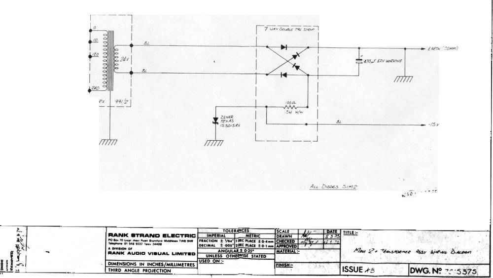
1.3 Mini-2+ Desk Power Supply (Drawing no. 7C15375)
Each portable 6-dimmer pack, and Perma 12 rack, contains an extra-low voltage power supply unit. The mains input to this, and the associated neon indicator, is protected by a cartridge fuse with a 500mA 20 x 5mm fuse-link (code 08 142 73 for a packet of 10). The smoothed and stabilised output is -15v DC; the positive rail is connected to earth/ground, as is the dimmer control common. On a multi-pack/rack installation each power supply feeds the desk in parallel, so that failure of all power supply units is necessary before the desk becomes inoperative. To prevent interaction all -15v DC supplies are diode blocked, at the desk, before being commoned.
1.4 Mini-2+/Perma 12 Dimmer Modules (Drawing no. 7C15376)
Mains supply to each module is via terminal block; numbers 1,2 and 3 for phase, neutral and earth\ground in that sequence. The dimmer output is terminal 4 (internal connection to output sockets on Mini-2+ modules). The dimmer control line is terminal 6. Dimmer control common is terminal 3 (earth\ground). A 0.1µf capacitor for RFI suppression is connected across terminal 2 (neutral) and terminal 4 (load).
1.5 Mini-2+ Desks (Drawing no. 7B15618)
These 2-preset desks contain no active electronic components. Channel fader levers are the double type with one fader each side of a common flat scale, with 10k Ohm strips, 10k Ohm fixed resistor and blocking diode (code 08 947 26, excluding knobs; 6 red and 6 green knobs code 08 947 85). Master faders are the single type with flat scale but have a 250 Ohm strip and no resistor or diode (code 08 947 34, supplied with 1 red and 1 green knob). Spare resistance strips are available, 10k Ohm code 08 947 42 for a packet of 10, or 250 Ohm, packet of 10, code 08 947 50. The colour code and pin numbers of the output cable and plug for each multiple of 6 channels correspond to the sequence given for the dimmer pack (see paragraph 1.1)
2. Setting Up Instructions
All this equipment is correctly set-up at the time of manufacture and no on-site adjustments should be necessary. However, should it be necessary for any reason the basic procedure is as follows :-
2.1 Dimmer Modules
2.1.1 Lamp load of at least 500W glowing when both dimmer levers at zero - bottom potentiometer VR1 set too high.
2.1.2 Lamp load of at least 500W no glow when control channel set to lever position 2 - bottom potentiometer VR1 set too low.
2.1.3 Lamp load of at least 500W reaching full light before control channel set to lever position 10 (i.e.dead travel at top) - top potentiometer VR2 set too high.
2.1.4 Lamp load of at least 500W not reaching full intensity when control channel set to lever position 10 - top potentiometer VR2 set too low.
2.1.5 The two potentiometers VR1 and VR2 are mounted on the trigger card of each module. On Mini-2+ packs, access is by removing the rear cover; on Perma 12 racks the large front cover provides access.
2.1.6VR1 is for bottom adjustment, VR2 for top adjustment. Clockwise rotation causes an increase of output, anti-clockwise a decrease. For example, for 2.1.1 above, VR1 should be turned anti-clockwise.
2.1.7 For accurate setting up of any Thyristor dimmer on output voltage a true RMS voltmeter (dynamometer or moving iron) is required. An AC multimeter, such as an AVO CAN be used but only as a comparison with a correctly set dimmer. With load of not less than 500W plugged in and the voltmeter connected either in the free socket or in numbers 2 and 4 in the terminal block, proceed as follows:-
2.1.8 With relevant master fader at full, set channel lever to 1, and adjust VR1 for an output of approximately 10 volts. (A better setting can be obtained if the setting potentiometer is rotated backwards and forwards a few times to clean the track before setting). With channel lever at 5, adjust VR2 for an output of 150 volts. Repeat 1 and 2 as necessary to achieve both settings.
2.1.9 With channel lever at 10, check that the output is within approximately 5 volts of mains voltage.
2.2 Control Desks
There are no adjustments to be made in the control desk as the network is entirely passive - see 1.5 for description.
Maintenance
3.1 Instruments
For voltage checks on various items the following instruments are required:-
- An AVO or similar AC/DC multimeter for power supply and desk checks.
- A dynamometer or moving-iron RMS voltmeter for dimmer output voltage checks and setting.
3.2 List of Drawings

